|
GAS/VAPOR and LIQUID FLOW CELLS |
|
|
|
|
|
|
|

|
Flow Cell Products |
Line and Space, Digit Length |
Designs |
Conductor |
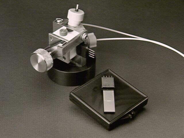
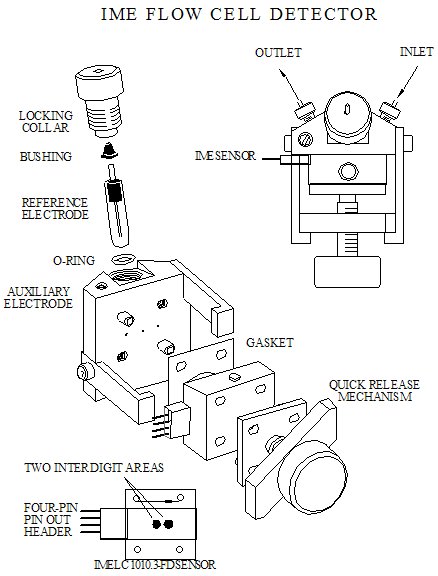
Liquid Flow Cell Detector (FCD) |
|
|
|
|
FCD 1010.3-FD Flow Cell Detector |
10 microns, 3 mm long |
10 bands |
Au, Pt |
|
IME 1010.3-FD-Au or Pt Flow Cell Sensor (refill sensor for Flow Cell Detector, FCD) |
10 microns, 3 mm long |
10 bands |
Au, Pt |
Controlled Environment Cell (CEC) |
|
|
|
|
CEC 1010.3-FD Controlled Environment Cell |
10 microns, 3 mm long |
10 bands |
Au, Pt |
|
IME 1010.3-FD-Au or Pt Flow Cell Sensor (refill sensor chip for Controlled Environment Cell, CEC) |
10 microns, 3 mm long |
10 bands |
Au, Pt |
|
CEC 1050.5-FD Controlled Environment Cell |
10 microns, 5 mm long |
50 bands |
Au, Pt |
|
IME 1050.5-FD-Au or Pt Flow Cell Sensor (refill sensor chip for Controlled Environment Cell, CEC) |
10 microns, 5 mm long |
50 bands |
Au, Pt |
|
|||||||||
|
Ø Chip Substrate: |
Schott D263 Borosilicate Glass |
||||||||
|
Dielectric Constant, Epsilon(r) at 1 MHz |
6.7 |
||||||||
|
Dielectric Loss Angle, tan delta, at 1 MHz |
61 x 10-4 |
||||||||
|
Electrical Resistivity (50 Hz) (250 C) |
1.6 x 10⁸ ohm cm |
||||||||
|
Coefficient of Linear Thermal Expansion, * 20-300 Deg C |
7.2 x 10^-6 K^-1 |
||||||||
|
Refractive Index at 20 C, ne ( Lambda = 546.1 nm) |
1.5249 |
||||||||
|
Ø Metallization: |
100 Å Ti|W / 1000 Å Au or Pt and ITO = 10 Ohms/sq |
||||||||
|
|
|||||||||
|
Ø IME SENSOR |
1010.3 |
1050.5 |
|||||||
|
|
Digit length, d, (microns) |
2990 |
4990 |
||||||
|
|
No. of digit pairs per sensor, N |
10 |
50 |
|
|||||
|
|
Digit Width, a, (microns) |
10 |
10 |
||||||
|
|
Interdigit Space, a, (microns) |
10 |
10 |
||||||
|
|
Spatial Periodicity, l lambda, (microns) |
40 |
40 |
||||||
|
|
Zaretsky Meander Length, M, (cm) |
2.99 |
24.95 |
||||||
|
|
Center Line or Serpentine Length (cm) |
5.72 |
49.6 |
||||||
|
|
Cell Constant (cm-1) |
0.33 |
0.04 |
||||||
|
|
Electrode Area; each bus (cm-2) |
3.03 x 10⁻³ |
2.50 x10⁻² |
||||||
|
|
Total Electrode Area; all busses (cm-2) |
1.21 x10⁻² |
9.98 x10⁻² |
||||||
|
|
Ø IME Chip Dimensions (l x w x t cm) |
|
|
||||||
|
|
Un-packaged Die |
3.10 x 1.00 x 0.05 cm |
2.00 x 1.00 x 0.05 cm |
||||||
|
|
Packaged Die |
4.20 x 1.25 x 0.55 cm |
3.10 x 1.25 x 0.55 cm |
||||||
|
Ø Packaging |
|||||||||
|
Electrode Body: |
PVC-Jacketed printed circuit board |
||||||||
|
Encapsulant: |
Epoxy header. Silicon nitride packaged chip. |
||||||||
|
Leadwires: |
Gold plated pins |
||||||||
Back to top |
|||||||||
|